SUB-AUDIO MAGNETICS (SAM)
• Simultaneous and rapid acquisition of physically independent data sets (magnetics, MMR and EM).
• High-resolution, fast production, incredibly scalable technique (Ground SAM, UAVSAM, HeliSAM, LakeSAM).
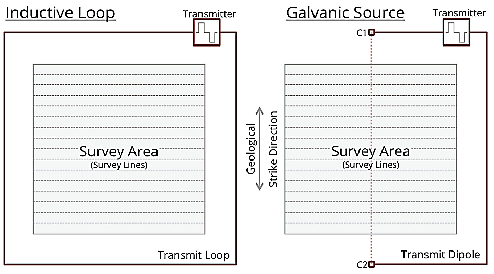
• Two primary modes of deployment – Galvanic dipole source (MMR), or inductive loop (EM)
• Can be used to see through highly conductive surface layers, such as salt lakes, which usually limits other electrical geophysics techniques.
 SUB-AUDIO MAGNETICS (SAM)
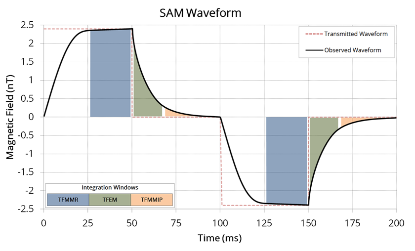
Sub-Audio Magnetics (SAM) is a proprietary survey technique which requires a geophysical transmitter to transmit a precisely controlled signal into either an inductive transmit loop or a grounded dipole in order to induce secondary fields in sub-surface conductors. Using Gap Geophysics’ (a Dias company) transmitters, currents of up to 200A are normally achieved with low resistance loops. Typically, 15-30A will be transmitted into a grounded dipole.
A Gap Geophysics TM-7 SAM Receiver is used to record the earth’s total magnetic field at sample rates up to 9600Hz. The TM-7 uses a caesium vapour magnetometer sensor which provides a scalar total field measurement without the requirement of levelling or orienting the sensor.
The acquired data is post-processed to extract several parameters which relate to different physical properties of the earth. The actual parameters available are dependent on the survey configuration and may include:
• Total Field MagnetoMetric Conductivity (TFMMC)
• Total Field ElectroMagnetics (TFEM)
• Total Field MagnetoMetric Induced Polarization (TFMMIP)
• Total Magnetic Intensity (TMI)
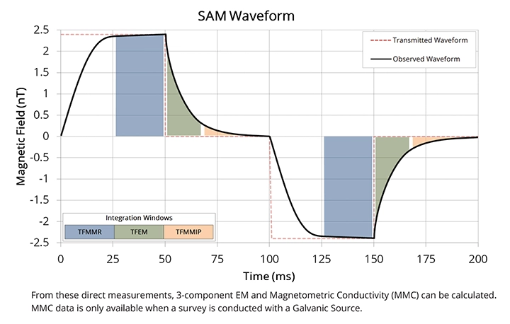
Each parameter extracted from a different part of the received waveform. TFMMC is an ON-time measurement as it occurs whilst current is being transmitted into the dipole where as TFEM and TFMMIP are OFF-time measurements as they occur whilst the transmitter is switched off. TMI is recovered from the low frequency component of the waveform.
SAM Magnetometric Conductivity (MMC) mode
In this survey layout, a galvanic loop is used to inject current directly into the ground, which enables SAM to deliver high definition Total Magnetic Intensity and Magnetometric Conductivity data sets.
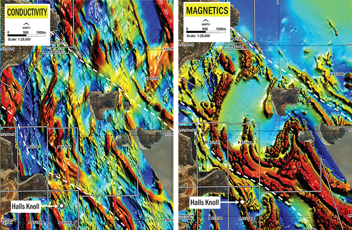
This type of survey better suits the detection of faults, fractures, and other geology that is detected by seeking resistive anomalies in conductive terrain.
SAM Fixed Loop Electromagnetics (FLEM) mode
In fixed loop mode, a high powered transmitter will send current through a closed loop, inducing a secondary field in the ground. SAM-FLEM delivers Total Magnetic Intensity, Total Field Electromagnetics and derived 3-component Electromagnetic data from one survey.
This technique is able to detect large conductors (such as massive sulphides) under far greater depth of cover than possible with conventional EM methods.
SAMSON
SAMSON utilizes our TM-7 receiver system to perform a time-domain electromagnetic survey using a total field cesium vapour sensor. It is based on our SAM technique, but instead acquires data through five minute acquisitions at fixed points, rather than being a moving survey.
In order to achieve extra low noise levels, surveys use one of Gap’s high powered transmitters. Developed in collaboration with EMIT, the system can operate at the very low base frequencies needed for determining the true late-time decay constant of a deep target.
Why Use SAMSON?
SAMSON is one of our most sensitive Deep Search techniques. Under ideal conditions, it brings mineral exploration to the limits of financially feasible depth-of-interest. SAMSON is capable of recording data at the background noise level – meaning that this existing commercial technology is touching on the limits of what is achievable for information discrimination.
SAMSON was developed for high conductance ore bodies such as Cu and Ni Sulphide deposits.
Fast Surveying at Greater Depth
From modelling studies, a large conductive target can be detected at depths approaching 1000m or more, even under conductive cover.
The setup and time at each station is very low as the total field (scalar) measurement allows for the surveys to be logistically simple. In-built navigation helps ensure efficient terrain traversal. Surveys can be carried out in rugged terrain without the need for a level pad for the sensor. Surveys can also be carried out in windy conditions.
Conductive Targets
The system is excellent at discriminating highly conductive targets – even when within conductive terrain. EMIT’s Maxwell software can easily model the total field EM responses.
Specifications
- Fixed loop or moving loop EM survey types
- Late time noise levels < 0.005pT/A (Gap Transmitter)
- Dipole, FLEM or MLEM Modes
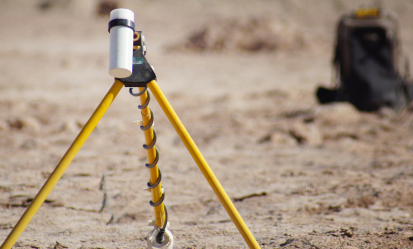
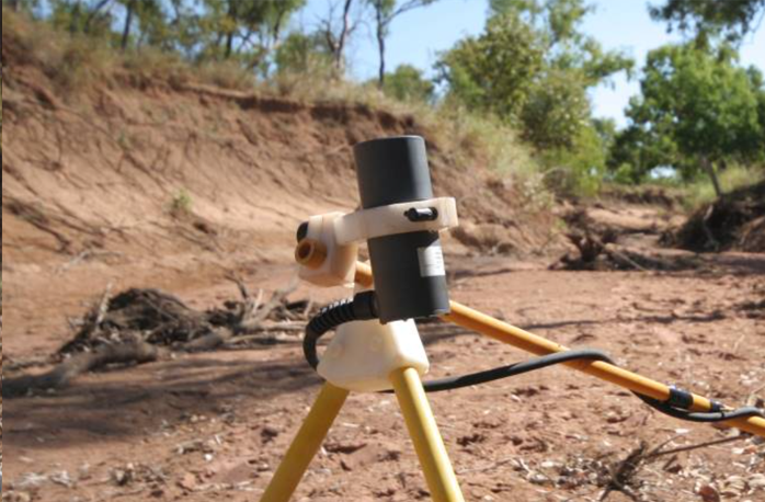
- Sensor is mounted on a tripod carried by operator
- No orientation, levelling or stable platform required
- Immune to wind and vibration
- Low Tx frequencies – typically 0.125 to 2Hz
- Typically 3-5 minute stations
- Acquisition Rate – typically 8-12 stations per hour
- Station Spacing – typically 50 – 100m
- Line Spacing – Typically 100 – 200m
- Logistically simple – lightweight, no cryogenic cooling required
- Logging time and stack time are preset in the SAMUI control software
- Real-time Quality Control
HeliSAM
HeliSAM refers to our airborne acquisition using a helicopter. HeliSAM is used commercially for large dipole (up to 12 km) SAM MMR / MMC surveys and for large scale SAM EM surveys.
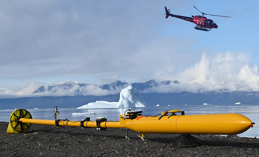
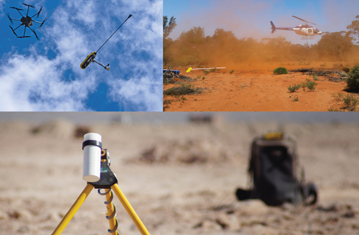
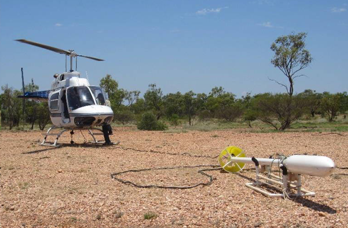
The HeliSAM system consists of the Cs sensor, GPS unit and laser altimeter mounted in a towed “bird” as shown in photo below. The bird is towed with a sling to mitigate interference from the helicopter. The sling length is typically 30m. No compensation is required for aircraft pitch, roll or yaw.
HeliSAM is used for large scale SAM MMR/MMC and FLEM surveys and typically uses Tx frequencies 3.125-15Hz. Achievable sample intervals are nominally 5.0m for TMI; 20m for MMR and TFEM (depending on Tx frequency).
Low frequency (LF) HeliSAM is a variant of HeliSAM where transmit frequencies as low as 2Hz are used. LF HeliSAM uses a 50m sling which enables the helicopter to fly at higher elevation above ground and at a slower speed.
HeliSAM achieves much greater production rates with typical survey speeds of 80 km/h. HeliSAM successfully detected the Lalor VMS deposit in Manitoba, Canada that lies between 700m – 1000m below surface.
Benefits
- Magnetic field measured up to 9600 readings/sec. (5cm. sample interval)
- Increased data resolution due to helicopters ability to fly lower and slower than traditionally used fixed wing systems
- High accuracy positioning & navigation – suitable for DTM data
- Towed bird system – no aircraft effect on magnetic data (no real-time or post processed compensation required)
- Quick data transfer from the field back to head office – same day preliminary grids available
- Helicopters superior contouring capabilities – uniform data resolution
- Minimal ferry due to ability to base close to survey area. Ideal for remote areas where no airstrips are available
- Digital video flight path available
- Aircraft equipped with satellite tracking for flight following
- Aircraft and support vehicle equipped with satellite phone and 2 way radio communications
- Experienced survey pilots and field crew
- Prompt system availability
Specifications
- DGPS positioning accuracy of 10cm horizontally and 15cm vertically
- Robinson R44 helicopter (turbine helicopter available on request)
- Sensor height 30m AGL (helicopter 60 m AGL) 2 diurnal base station magnetometers
- Support ground crew and vehicle
- In-field data quality control
 UAV SAM
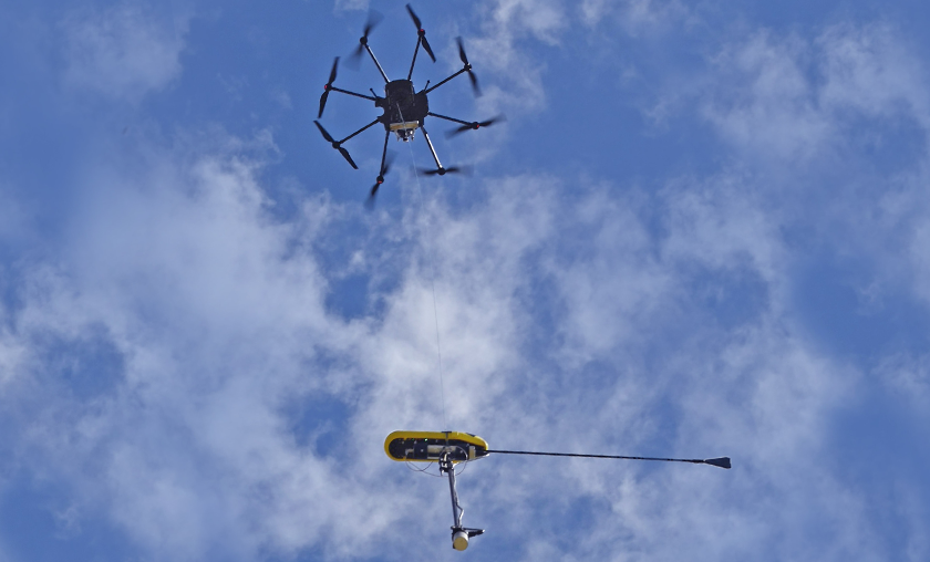
UAVSAM refers to semi-airborne acquisition of the SAM geophysical technique, using an unmanned aerial vehicle (UAV). UAVSAM is used commercially for SAM MMR / MMC surveys, SAM Fixed-Loop EM surveys, and SAM Moving Loop EM surveys that require a low impact or are complicated by ground hazards.
The UAVSAM system consists of a Cs sensor, GPS unit augmented with an IMU system, and laser altimeter mounted in a towed “bird” as shown in the photo below. The receiver bird sling is approximately 20m long to mitigate electrical interference from the UAV engine. No compensation is required for UAV pitch, roll, or yaw as it is a total B field magnetometer.
Benefits
- UAVSAM can effectively increase the data density of traditional EM surveys while reducing the amount of time spent during data acquisition in areas of rough terrain. Additionally, the need for line clearing/cutting can be reduced significantly as ground crews no longer need to traverse the survey lines.
- The UAVSAM system acquires data at speeds between 4 and 10 m/s and provides incredibly high-resolution data over conventional techniques. UAVSAM is capable of surveying between 1 and 12.5 Hz transmit frequencies, covering a wide range of applications in mineral exploration. The UAV system has been successfully tested at the Forrestania EM test range (in Australia), showcasing very high data density and reduced survey duration due to the logistical simplicity of deploying a UAV platform.
SAM B-Field Technologies summarized

Differences in survey lines
